Level Transmitter Service

Beach Electrical offers professional level transmitter service for industrial tanks and vessels. Our technicians provide expert installation, wiring, and calibration for your Felton, CA facility.
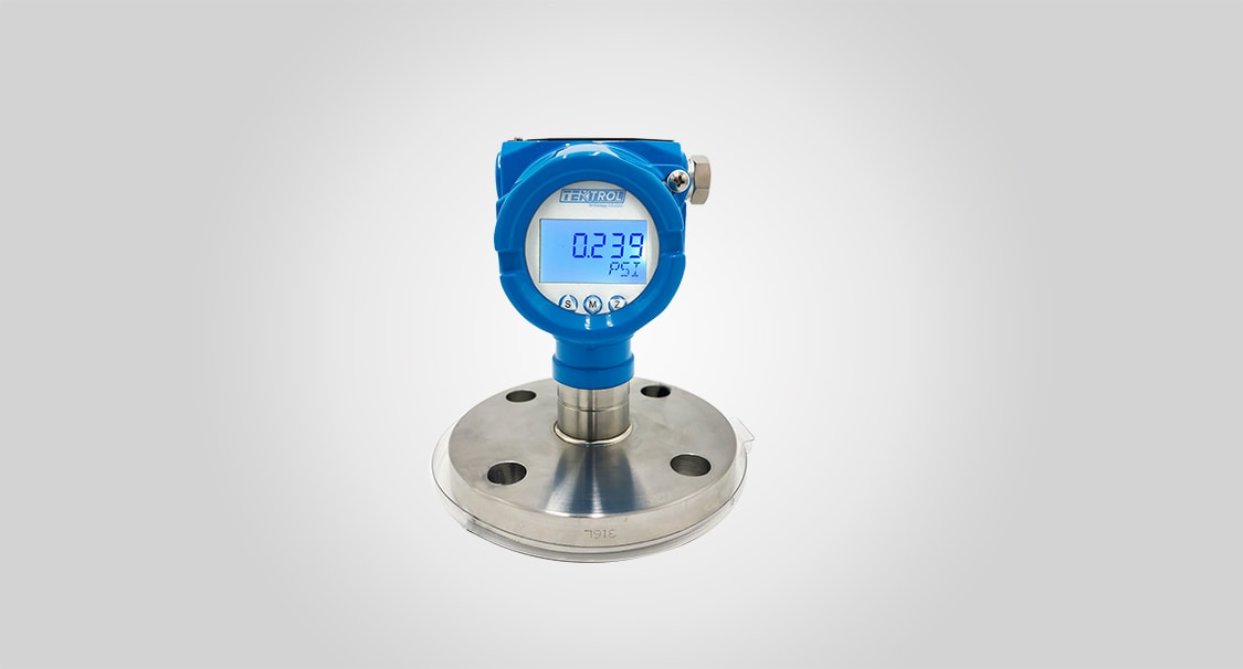
Level Transmitter Service photo courtesy of Tek-Trol LLC.

Top Level Transmitter Service in Felton, CA

Accurate and reliable level measurement is essential for inventory management, process control, and preventing dangerous spills or overflows in any industrial facility. A properly functioning level transmitter provides this critical data. Beach Electrical offers a complete range of level transmitter services for our industrial clients. With over 30 years of experience, our instrumentation technicians are proficient in the installation, wiring, and calibration of all major level measurement technologies. We work with ultrasonic, radar, and pressure based level systems. As 70E and OSHA 30 certified professionals, we always perform our work to the highest safety standards. Ensure the reliability of your critical level measurements with expert service from Beach Electrical in Felton.

google
Meenu Agroia
July 29, 2025
google
Jeanette Guire
January 22, 2025
google
Faith Reid
January 6, 2025
google
Paul M
October 12, 2024
google
Carol Patten
August 23, 2024
google
Janice Gidcumb
June 20, 2024
google
Jeff Hall
April 4, 2024
google
cherie hung
March 29, 2024
google
Joseph Beasley
March 28, 2024
google
Betsy Wootten
March 27, 2024

Our Level Transmitter Service Locations

Beach Electrical is proud to offer expert level transmitter services to our valued clients throughout the region. We are committed to providing reliable electrical solutions to numerous communities. Below you will find a complete list of the cities and towns we serve.

Years of experience
Client Satisfaction
homes inspected
Completed Service Calls

Level Transmitter Service in Felton, CA

Another advanced non contact technology is radar level measurement. Radar works on a similar principle to ultrasonic, but instead of a sound pulse, it uses a microwave radar pulse. Radar has several advantages over ultrasonic in certain applications. It is unaffected by changes in air temperature, pressure, or humidity within the tank, and it can “see” through heavy vapors or dust that might interfere with an ultrasonic signal. Guided wave radar is a related technology that uses a probe or cable that extends down into the tank to guide the radar pulse, which makes it extremely accurate and reliable even in turbulent conditions.

A more traditional method for measuring liquid level is by using a pressure transmitter. A pressure transmitter can be mounted at the bottom of an open, vented tank. It measures the hydrostatic pressure exerted by the column of liquid above it. Since this pressure is directly proportional to the height of the liquid, the transmitter can calculate the level. For pressurized tanks, a differential pressure (DP) transmitter is used, which measures the difference in pressure between the bottom of the tank and the vapor space at the top.

Our level transmitter services include the complete installation of new instruments. We will properly mount the sensor on your tank, whether it is on a flanged nozzle on the top or a threaded connection at the bottom. We then run the necessary power and signal wiring from the transmitter back to your control panel. We take great care to run the shielded signal cable in a way that protects it from electrical noise, ensuring a stable and reliable measurement. We then connect the instrument to the correct input on your PLC or other control system.

Calibration is a key part of our service. After a new transmitter is installed, or as part of a regular maintenance schedule, we will perform a calibration to ensure its accuracy. This typically involves setting the “zero” and “span” of the instrument. For example, with the tank empty, we will adjust the transmitter so its output is 4 mA. Then, with the tank full, we will adjust the output to 20 mA. This ensures that the instrument’s output accurately represents the real world level across its entire operating range.

A faulty level transmitter can lead to serious process upsets, dangerous spills, or costly production losses. If you are experiencing problems with an existing level measurement system, our skilled technicians can provide expert troubleshooting and repair services. We can diagnose the root cause of the problem, whether it is a failed sensor, a faulty transmitter, a wiring issue, or a configuration error, and perform the necessary repairs to get your system back online. Trust Beach Electrical for all your level instrumentation needs in Felton.

What Makes a Great Level Transmitter Service

A great level transmitter service requires expertise in the various measurement technologies and the precision to install and calibrate them correctly. Beach Electrical ensures your level instruments provide accurate, repeatable data.

  • Multi-Technology Expertise: Proficient with ultrasonic, radar, guided wave, and pressure level systems.
  • Proper Installation and Mounting: We know how to correctly mount sensors for optimal performance.
  • Precision Wiring for Clean Signals: We run and shield signal cables to eliminate electrical noise.
  • Expert Calibration Services: We can perform zero and span calibrations to ensure measurement accuracy.
  • Industrial Safety and Experience: Our 70E certified technicians are at home in any plant environment.

Most Common Level Transmitter Service Questions

Level transmitters are a cornerstone of industrial automation, providing critical data for inventory and process control. For those new to instrumentation, the various technologies can be a source of questions. The following answers explain some of the key concepts and technologies in industrial level measurement.

A level transmitter is a specialized industrial instrument that is designed to measure the height of a substance, such as a liquid, slurry, or powder, inside a tank, silo, or other vessel, and then convert that measurement into a standardized electrical signal. Its primary job is to provide continuous, real time information about how “full” a vessel is. This information is then typically sent to a central control system, like a PLC, or to a local display panel.

This level data is used for a variety of critical purposes in an industrial plant. It is used for inventory management, allowing operators to know exactly how much raw material or finished product they have in their storage tanks. It is used for process control, where the level in a reactor vessel might need to be maintained at a specific setpoint. It is also used for safety. A level transmitter can be connected to high level and low level alarms to alert operators and prevent a dangerous overflow or to shut down a pump to prevent it from running dry.

Level transmitters are used in virtually every industry, including chemical processing, food and beverage, pharmaceuticals, water and wastewater treatment, and power generation. The reliability and accuracy of the level measurement are often essential for the safe and efficient operation of the entire process.

Ultrasonic and radar level transmitters are both popular non contact technologies, meaning their sensors are mounted on top of a tank and measure the level without ever touching the substance. The primary difference between them is the type of wave they use to make the measurement. An ultrasonic level transmitter uses a high frequency sound wave, while a radar level transmitter uses a high frequency electromagnetic (radio) wave.

An ultrasonic transmitter works by sending a short burst of sound down towards the surface of the liquid. The sound wave reflects off the surface and travels back up to the sensor. The transmitter measures the total time it took for the sound to make this round trip. Since the speed of sound in the air inside the tank is known, the transmitter can use this time measurement to calculate the distance to the surface with high accuracy.

A radar transmitter works in a very similar way, but it sends out a microwave pulse instead of a sound pulse. This use of electromagnetic waves gives radar some key advantages in certain challenging applications. The speed of a radar wave is not affected by changes in the temperature, pressure, or humidity of the gas or vapor space inside the tank, whereas the speed of a sound wave is. This makes radar more accurate in applications with changing atmospheric conditions. Radar waves can also penetrate through heavy dust, vapor, and foam that might absorb or scatter an ultrasonic signal.

A guided wave radar (GWR) transmitter is an advanced and highly accurate type of level measurement technology that combines the principles of radar with a physical probe. Unlike a standard, non contact radar transmitter that sends its signal out through the air, a GWR transmitter uses a rigid rod or a flexible cable probe that is mounted on the top of the tank and extends all the way down to the bottom of the vessel.

The GWR transmitter sends a low energy microwave radar pulse down this probe, or “waveguide.” The probe’s function is to guide the radar pulse in a straight, focused path down to the liquid surface. When the pulse hits the surface of the liquid, a significant portion of its energy is reflected back up the probe to the transmitter. The transmitter’s electronics measure the very short time it takes for this pulse to travel down and back. This time measurement is then used to calculate the exact distance to the liquid surface with very high precision.

The main advantage of guiding the radar pulse is that it makes the measurement extremely reliable and immune to many of the problems that can affect non contact technologies. The measurement is not affected by turbulence on the liquid surface, foam, or heavy vapors in the tank. This makes GWR an excellent choice for difficult applications with challenging process conditions. It can also be used for measuring the level of solids or for detecting the interface level between two different liquids, like oil and water.

Calibrating a level transmitter is the process of adjusting it to ensure that its electrical output signal accurately corresponds to the actual physical level in the tank. The most common calibration procedure for a 4 to 20mA transmitter is to perform a “two point” calibration by setting the zero and span points. The “zero” point is the level in the tank that you want to correspond to the 4 mA output, and the “span” or “full scale” point is the level that you want to correspond to the 20 mA output.

The ideal way to perform this calibration is with the actual process. This involves first bringing the tank to the desired low level point (the zero point), which may be the empty state or the normal low operating level. A technician then uses a handheld communicator or software to adjust the transmitter so that its output is exactly 4.0 mA. Then, the tank is filled to the desired high level point (the span point). The technician then adjusts the transmitter again so that its output is exactly 20.0 mA.

If it is not practical to fill and empty the tank for the calibration, a “bench” calibration can be performed. The transmitter is removed from the tank and set up on a workbench. For a non contact ultrasonic or radar transmitter, a technician will use a flat target and place it at the known zero and span distances from the sensor to perform the adjustments. For a pressure based level transmitter, a pressure calibrator is used to apply the known low and high pressures that correspond to the empty and full tank levels.

An incorrect or unstable reading from a level transmitter can be caused by a wide range of issues, and troubleshooting the problem requires a methodical approach. The first place to look is at the physical installation of the sensor. For a non contact ultrasonic or radar sensor, it must be mounted perfectly perpendicular to the liquid surface and in a location that has a clear, unobstructed view of the surface. Any internal obstructions in the tank, such as pipes, ladders, or agitator blades, can create false echoes that can confuse the sensor.

The process conditions inside the tank are another common source of problems. Heavy foam on the surface of the liquid can absorb the signal from an ultrasonic or radar sensor, causing it to lose the echo. Extreme turbulence on the surface can also make it difficult for the sensor to get a consistent reading. For an ultrasonic transmitter, heavy dust or vapor in the tank can interfere with the sound wave. For a pressure based level transmitter, a clogged impulse line or a buildup of sludge covering the sensor’s diaphragm are common causes of inaccurate readings.

Electrical issues are also a frequent culprit. Electrical noise being induced on the signal cable can cause the reading to be very erratic and “jumpy.” This is often caused by running the instrument cable too close to high power motor wiring. A poor connection at a terminal block or a problem with the 24 volt DC power supply can also cause a variety of issues. Finally, the problem could be in the transmitter’s configuration; an incorrect setting for the tank height or another parameter can lead to a reading that is consistently wrong.

A differential pressure (DP) level transmitter is a specific type of pressure based instrument that is used to measure the level of a liquid in a pressurized or sealed vessel. In an open tank that is vented to the atmosphere, you can measure the level by simply placing a single pressure sensor at the bottom to measure the hydrostatic head pressure. However, in a sealed tank, there is often a variable gas or vapor pressure in the space above the liquid. This “blanket pressure” will also press down on the liquid and will be added to the hydrostatic pressure measurement, which would make a single pressure sensor’s reading inaccurate.

A DP transmitter solves this problem by using two pressure sensors. One sensor, called the “high side,” is connected to a tap at the bottom of the tank. This sensor measures the total pressure at the bottom, which is the sum of the hydrostatic liquid pressure and the blanket pressure. The second sensor, called the “low side,” is connected to a tap at the top of the tank, in the vapor space. This sensor measures only the blanket pressure.

The DP transmitter’s electronics then subtract the low side pressure reading from the high side pressure reading. This subtraction cancels out the effect of the blanket pressure, leaving only the true hydrostatic pressure of the liquid column. The transmitter can then use this corrected hydrostatic pressure reading to accurately calculate the liquid level. DP transmitters are a very common and reliable way to measure level in a wide variety of industrial applications.

The proper installation of a non contact level sensor, such as an ultrasonic or radar transmitter, is critical for achieving an accurate and reliable measurement. The first step is to select the correct mounting location on the top of the tank. The sensor should be mounted in a location that has a clear, unobstructed “line of sight” to the surface of the material being measured. You must avoid any internal obstructions like inlet pipes, ladders, support beams, or agitator shafts, as these can create false echoes and interfere with the measurement.

The sensor must also be mounted so that it is perfectly perpendicular (at a 90 degree angle) to the liquid surface. If the sensor is mounted at an angle, its signal may reflect off the surface at an angle and not return directly to the sensor, resulting in a lost signal. It should also be mounted away from the tank wall to avoid interference from the wall. Most manufacturers provide a recommended minimum distance from the wall.

The sensor is typically mounted on a flanged nozzle or a threaded connection on the top of the tank. It is important that the end of the nozzle does not extend too far into the tank, as this can create a “dead zone” where the sensor cannot measure. The sensor needs a certain minimum distance to operate, which is called its “blanking distance.” After the sensor is mechanically mounted, the electrical wiring for power and the 4 to 20mA signal is run back to the control panel, typically in a dedicated, shielded conduit.

The wiring requirements for a typical modern level transmitter are similar to those for most other industrial instruments. The most common type of transmitter is a two wire, loop powered 4 to 20mA device. This means that both the 24 volt DC power for the instrument and its analog output signal are carried over the same pair of wires. This simplifies the field wiring, as only a single two conductor cable is needed to connect the transmitter to the PLC or control system.

The cable used for this connection should be a high quality, shielded, twisted pair instrumentation cable. The twisted pair configuration is very important as it helps to reject electromagnetic interference (EMI) from sources like motors and VFDs. The shield, which is usually a foil layer around the wires, protects the signal from radio frequency interference (RFI). For the shield to be effective, it must be properly grounded at only one end of the cable run, which is almost always the control panel end.

This instrumentation cable should be run in its own dedicated metal conduit to provide physical protection and additional electrical shielding. It should never be run in the same conduit as high voltage power wiring. The connections at both the transmitter’s terminal block and the PLC’s analog input card must be made securely. A loose connection in a 4 to 20mA loop can cause the reading to be intermittent or to fail completely.

Get The Top Level Transmitter Service Near You

For a free, no obligation estimate on your level transmitter service project, book a call back using our 24/7 self service system or call Beach Electrical directly at (831) 246-4014 today.